 Projects
 Bulk
Bulk Break Bulk
 Freight
 Trucking
Length
Length between perpendiculars (
Load line length (
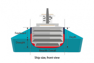
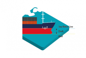
Beam ( breadth) ( B) = width of the hull usually measured inside shell plating (
Depth ( H) = height from baseline to uppermost deck at side measured inside the plating
Draught ( T) = underwater depth of a vessel
- Draught at the stern ( Ta) is the vertical distance between water line and keel plate ( immersion in water of the vessel) measured on the aft perpendicular;
- Draught forward ( Tfwd) is the vertical distance between
water line and keel plate ( immersion in water of the vessel) measured on the forward perpendicular.
Trim
It is the difference between the draught at stem ( forward) and the draught at the stern;
A vessel could be:
- Down and trimmed by the head, i. e. the draught at
forward is larger than the one at the stern; - Down and trimmed by the stem, i. e. the draught at the stern is larger than the one at the forward.
- Even keel is the situation where the trim equals zero, i. e. the draught at the stern equals the draught at the stem.
Proportions
- L/ B- The ratio of length and breadth: L/ B can differ quite significantly depending on the type of vessel. Common values are 6- 8 for passenger ships; 5- 7 for cargo ships; and 3- 5 for
tug boats . A larger value of L/ B isfavourable forspeed, butunfavourable formanoeuvrability . - L/ D– The length/ depth- ratio varies between 10 and 15. This relation plays a role in the determination of the freeboard and the longitudinal strength.
- B/ T– The breadth/ draught- ratio varies between 2 and 4. 5. A larger breadth in relation to the draught ( a larger B/ T value) gives a greater initial stability.
- B/ D– The breadth/ depth ratio varies between 1 and 2. If this value becomes larger, it will have an
unfavourable effect on the stability ( because the deck edge willbe emerged when the vessel heels) and on the strength.
Moulded dimensions
Distance measured a tin side of the shell plating ( i. e. distance measured between 2 points excluding the plate thickness)
Base Line
Measured imaginary horizontal
Deck Line
Horizontal line marked usually at the top of the main deck/
Load Line
Waterline of a vessel immersed in water:
- Light water line is the water line of a vessel carrying only her regular inventory
- Deep waterline/ summer water line is the water line of a vessel at the maximum draught in salt water
- Construction ( scantling) water line is the water line used as the limit to which the structural components of a vessel are designed.
Air draught
Vertical distance between the water line and the highest point of the vessel
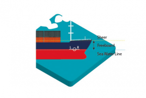
Freeboard Mark
Shows the maximum allowed value of a sinking ship, leaving enough space for safety. Lloyd’ s Register of British and Foreign Shipping was the first to introduce loading recommendations in 1835.
In 1860 Samuel Plimsoll ( 10 February 1824 – 3 June 1898
Merchant Shipping
In the 1930 Load Line Convention, the application of load line regulations became international. Later on, in 1966 during the Load Line Convention held in London, the rules of 1930 were
- The
free board is marked according to the result of the freeboard calculation ( which takes into account the main parameters such as length, beam ( breadth), sheer, length of superstructures etc.) ; the scope of the freeboard calculation is to establish the summer freeboard in salt water; - The load line markings must be permanently visible on the shell plating of the vessel;
- The abbreviations of the marked load lines have to be in the language of the flag state of the vessel;
- When a vessel carries timber cargo on deck and certain demands are met, the ship is allowed to have more draught ( less freeboard
) . The mark used for such cases is known as the Timber Mark;